
 English
 Español
 русский
News
Home / News / Industry News / Cold Forging, Hot Forging & Ring Forging: Processes, Comparisons & Steel Guide
"Cold forged" describes a metal part that has been shaped through a forging process carried out at or near room temperature — without the application of external heat to soften the workpiece. When a component is described as cold forged, it means the metal was plastically deformed under high compressive force while remaining below its recrystallization temperature, which for most steel alloys is approximately 700–750°C. The metal flows into a die cavity and takes the shape of the tool under pressures typically ranging from 400 MPa to over 2,500 MPa depending on material and geometry.
The defining characteristic of cold forged parts is the metallurgical effect of that cold deformation: work hardening. As the metal is compressed and forced to flow, its grain structure is refined and elongated in the direction of material flow. Dislocations within the crystal lattice multiply and impede further dislocation movement, resulting in a measurable increase in yield strength and hardness compared to the original billet material — often 20–40% higher than the annealed base material — without any change in chemical composition.
Cold forged components are found in automotive drivetrains (constant velocity joint housings, gear blanks, pinion shafts), fasteners (bolts, nuts, screws produced by cold heading), bicycle components, hand tool bodies, and precision hardware across industrial and consumer applications. The combination of near-net-shape dimensional accuracy, excellent surface finish, and enhanced mechanical properties makes cold forging one of the most materially efficient and mechanically effective manufacturing processes available for medium-to-high volume metal part production.
The hot vs cold forging decision is one of the most consequential choices in metal part manufacturing. Both processes use compressive force to shape metal, but they operate on fundamentally different metallurgical principles and deliver distinct outcomes across dimensional accuracy, surface quality, mechanical properties, tooling life, and material suitability.
| Variable | Cold Forging | Hot Forging |
|---|---|---|
| Working temperature | Room temperature to ~150°C | 800–1,250°C (material-dependent) |
| Dimensional tolerance | ±0.05–0.2 mm; near-net-shape | ±0.5–2.0 mm; requires machining allowance |
| Surface finish | Ra 0.4–1.6 µm; bright, scale-free | Ra 3.2–12.5 µm; scale and oxide present |
| Mechanical strength | Higher; work hardening increases yield strength | Good grain refinement; lower than cold forged for same alloy |
| Material ductility required | High; limited to low-to-medium carbon steels, aluminum, copper | Low; suitable for virtually all forgeable alloys including high-alloy steels |
| Part size range | Typically under 10 kg; best under 2 kg | From grams to hundreds of tonnes |
| Tooling cost | High (hardened tool steel, precision ground) | Moderate; dies operate at elevated temperature |
| Tooling life | 50,000–500,000+ parts per die set | 10,000–100,000 parts; thermal fatigue limits life |
| Energy consumption | Lower (no heating energy required) | Higher (furnace heating of billet adds 15–30% to process energy) |
| Post-forging machining | Minimal; often none for functional surfaces | Significant; scale removal, dimensional correction required |
A third category — warm forging — occupies the space between the two, with workpiece temperatures of 500–800°C for steel. Warm forging reduces the forming forces required compared to cold forging (by 30–50%) while still achieving tighter tolerances and better surface finish than hot forging. It is increasingly used for medium-carbon and alloy steel parts that exceed the ductility limits of cold forging but do not warrant full hot forging economics.
The hot vs cold forging decision ultimately reduces to three primary filters: material composition (is the alloy cold-forgeable?), part geometry and size (can the required shape be achieved within cold forging press force limits?), and volume economics (does the production run justify the higher cold forging tooling investment through per-unit savings on machining and material?).
Carbon steel is the most widely forged material class globally, accounting for the majority of forged industrial components by volume. Its forgability, cost, and broad mechanical property range make it suitable for both hot and cold forging across a wide range of structural, mechanical, and wear applications. Understanding which carbon steel grades are appropriate for each forging method is fundamental to part design and procurement.
Low carbon grades such as SAE 1010, 1015, and 1020 are the most commonly cold forged steels. Their high ductility (elongation of 25–35%) allows large plastic deformation without cracking, and their relatively low flow stress reduces press tonnage requirements. Cold forged low carbon steel parts achieve tensile strengths of 380–520 MPa after forging without heat treatment. Typical applications include fasteners, pins, brackets, and light structural hardware. The trade-off is limited hardenability — low carbon steels cannot be through-hardened by heat treatment, restricting their use in high-stress or wear-critical applications.
Grades such as SAE 1035, 1045, and 1060 offer a significantly higher strength ceiling after heat treatment — tensile strengths of 700–1,000 MPa are achievable in quenched-and-tempered condition — but their reduced ductility and higher flow stress make cold forging increasingly difficult above 0.35% carbon. Medium carbon steels are the dominant material for hot forged automotive components: crankshafts, connecting rods, axle shafts, gear blanks, and suspension knuckles. Forging carbon steel in this range at 1,100–1,250°C allows large, complex shapes to be formed in a single heat with excellent grain flow continuity through the part cross-section.
High carbon grades are forged primarily for tooling, springs, rail components, and cutting implements. Their brittleness at room temperature makes cold forging impractical for most geometries; hot forging at carefully controlled temperatures (900–1,100°C) is standard. Post-forging heat treatment — typically hardening and tempering or isothermal annealing — is mandatory to develop the intended mechanical properties and relieve forging stresses. Decarburization during hot forging (loss of surface carbon due to oxidation at elevated temperature) is a critical quality control concern for high carbon steels, requiring controlled atmosphere furnaces or protective coatings during heating.
The most important structural benefit of forging carbon steel — versus machining from bar stock or casting — is the continuous, contoured grain flow that results from plastic deformation. In a forged part, the grain structure follows the part contour, meaning that the highest-stress sections of the part align with the direction of maximum grain continuity. This produces fatigue resistance and impact toughness 20–40% superior to equivalent machined bar stock, and is the reason forged carbon steel is specified wherever cyclic loading, impact, or safety criticality is a design requirement.
The cold forging process is a multi-stage production sequence, not a single pressing operation. Achieving the final part geometry typically requires three to eight sequential forming stations, each advancing the workpiece incrementally toward the finished shape while managing work hardening and material flow distribution. A complete cold forging process sequence includes:
Cold forging feedstock arrives as coiled wire rod or cut bar stock. The material must be spheroidize-annealed prior to forging to maximize ductility and minimize flow stress — a heat treatment that converts the steel's carbide microstructure into a globular (spheroidized) form, reducing hardness to typically 70–90 HRB. Billet cutting must produce consistent weight and square-cut ends to ensure uniform volume distribution in the die cavities.
Lubrication is the most technically critical variable in the cold forging process. Without adequate lubrication, friction between the workpiece and die surface generates heat, accelerates die wear, and causes surface defects on the forged part. The standard lubrication system for steel cold forging involves three steps: phosphate conversion coating of the billet surface (creating a porous zinc or manganese phosphate layer 3–10 µm thick), followed by reactive soap lubrication (sodium stearate), which bonds chemically to the phosphate layer and provides the boundary lubrication film that separates metal from die during forming. This phosphate-soap system reduces die friction coefficients from 0.12–0.18 to 0.03–0.06, enabling the high reductions in area required for complex shapes.
The lubricated billet is transferred through a series of forming stations, each performing a defined deformation operation. Common cold forging operations include forward extrusion (material flows in the direction of punch travel, reducing cross-section), backward extrusion (material flows opposite to punch travel, forming hollow cups and sleeves), upsetting (compressing billet length to increase diameter, as in bolt head formation), ironing (reducing wall thickness with precise dimensional control), and coining (a final sizing and surface finishing operation under very high pressure). Each station is designed to keep deformation within the material's strain capacity per pass — typically 60–75% reduction in area maximum before an intermediate anneal is required to restore ductility.
For complex parts requiring total reductions in area exceeding 75%, an intermediate spheroidize anneal is performed between forming stages to restore ductility before continuing. This adds cost and cycle time but is essential for avoiding cracking in highly work-hardened material. Modern cold forging process design seeks to minimize the number of intermediate anneals through optimized material selection and forming sequence planning.
After forming, cold forged parts typically undergo trimming or piercing to remove flash or open holes, followed by heat treatment if elevated strength or hardness beyond work-hardened levels is required. Dimensional inspection uses CMM (coordinate measuring machine) verification for first-article approval and statistical process control sampling during production. Surface crack detection by magnetic particle inspection (MPI) or dye penetrant testing (DPT) is mandatory for safety-critical applications including automotive structural and powertrain components. Tool wear monitoring — tracking punch and die dimensions against tolerance limits — is standard practice in high-volume cold forging operations, as gradual die wear is the primary cause of dimensional drift between first-article approval and end-of-tool-life production.
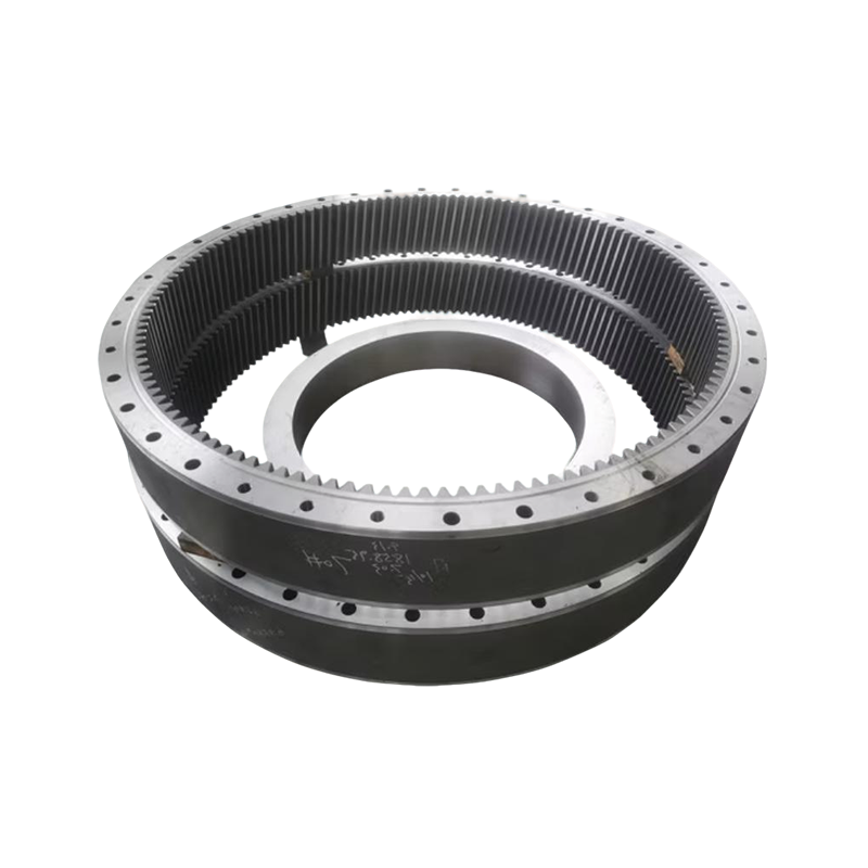
Ring forging is a specialized hot forging process used to produce seamless rings with continuous, circumferential grain flow — a structural configuration that no other manufacturing process can replicate. Forged rings are used wherever high strength, fatigue resistance, and dimensional integrity under cyclic or pressure loading are required: bearing races, gear rings, flanges, pressure vessel heads, pipeline coupling flanges, turbine engine casings, wind turbine slewing rings, and rotating rings for aerospace structural frames.
Ring forging is produced through a process called ring rolling, which proceeds in the following sequence. A cylindrical billet is first upset (compressed axially) to increase diameter and reduce height. A piercing punch then creates a central hole through the billet, producing a thick-walled preform ring (the "donut"). This preform is heated to forging temperature and placed on a ring rolling mill, where it is positioned between a driven main roll and an idle mandrel roll. As the main roll rotates and the mandrel advances radially, the ring wall is progressively reduced in thickness while diameter increases. Axial rolls (cone rolls) simultaneously control ring height. The ring grows continuously in diameter — from a preform of perhaps 200 mm to a finished ring of 2,000 mm or more — while wall thickness and height converge to final dimensions.
Throughout this process, the metal's grain structure develops a circumferential orientation that follows the ring contour exactly. In a machined ring cut from bar or plate, grain lines run straight through the part — meaning grain boundaries cross the highly stressed bore and outer diameter surfaces at oblique angles. In a ring forged component, grain flow is parallel to all critical surfaces, maximizing fatigue crack resistance, hoop strength, and pressure-bearing capacity at every point around the circumference.
Ring forging is one of the most scale-flexible metal forming processes available. Forged rings are produced in outside diameters ranging from under 100 mm (small bearing races, hydraulic fittings) to over 9,000 mm (large wind turbine main bearings, reactor pressure vessel flanges). Wall thickness can be as thin as 10 mm or as heavy as 500+ mm depending on application. Materials routinely ring forged include carbon and alloy steels, stainless steels (austenitic, martensitic, and duplex grades), nickel-based superalloys (Inconel 718, Waspaloy) for aerospace and power generation, titanium alloys for aerospace structural rings, and aluminum alloys for lightweight structural applications.
The principal alternatives to ring forging for annular components are machining from solid bar or plate, welding from rolled plate, and centrifugal casting. Each carries significant disadvantages in safety-critical applications:
For these reasons, design codes governing pressure vessels (ASME Section VIII), rotating machinery (API standards), aerospace structures (AMS specifications), and wind turbine components (IEC 61400 series) mandate ring forged construction for critical annular components — making ring forging not merely a preferred option but a compliance requirement in regulated industries.
No.1317 Gangcheng Road, Daxin Town, Zhangjiagang, Jiangsu, China
WhatsApp:+86-151 5156 6388 Terry Huang
+86-151 5156 6388 Terry Huang
+86-138 1299 2607 Maggie Xia
Terry Huang -VP of Sales
[email protected]
Maggie Xia -VP of Sales
[email protected]


